
Description
Instructional Objectives:
· To learn how to write a structured program
· To learn what is meant by top-down design
· To learn how to break a programming task into modules and to learn the advantages of such
an approach
· To enhance your ability to write, test, and debug HC(S)12 assembly code
Prelab Preparation:
Read this document in its entirety
Write the code for all steps prior to coming to lab
Introduction:
As the jobs we desire the 9S12C32 to do become larger, it becomes more and more complicated to write and debug the code. One technique for overcoming these complications (or at least simplifying the problem) is modular programming. The idea behind modular programming is to break the job into small tasks and, if needed, break these into even smaller sub-tasks. The basic premise is that smaller tasks are easier to code, test, and debug.
The toughest part of modularizing your code is often deciding how to break it into appropriatelysized
modules. The technique we propose you use is top-down programming. “Top-down” simply means start at the “top” (the “big picture”) and work your way “down” to the bottom (the “program pieces”). In other words, first write a “main” (or “supervisor”) code module that calls various sub-modules. Each of these sub-modules performs a specific task. Each task may be quite independent of the others. This makes it easy to program each one separately. It may be
helpful to even break these sub-modules into several lower-level “chunks”. Each “chunk” will perform a single job and will probably not exceed much more than 10 to 15 lines of code. These chunks will perform the elementary tasks needed by the “main” program. For example, a “code chunk” may include reading a value from the terminal keyboard or converting an ASCII value to a hex value. The important thing to note is that most all of these “code chunks” can be independently tested, debugged, and verified. As you test and verify various “code chunks”, you can successively incorporate these modules into your main program (note that “include” files can be utilized to help facilitate this process). For routines not yet written, simply write a “dummy module” that merely returns or prints a message to the effect that the module has been reached.
If you wish execution to terminate when one of these yet-to-be-completed sub-modules is reached, simply set a breakpoint in that “dummy module”.
In this experiment, you will create a “Mini-Monitor” (operating system) that executes out of flash memory upon power-on/reset. Features of this monitor will include a memory editor, a memory display command, a register display command, and a “go” command.
ECE 362 – Experiment 4 Rev 1/13
Bigger Bytes Lab Manual -2- © 2013 by D. G. Meyer
Program Description:
A “monitor” program is a small, resident operating system that can be used to load, run, and debug application programs on a target microcontroller system. For this experiment, you will combine a memory editor with some other basic functions (go, memory display, register display) to create a reasonably useful monitor program for use on the 9S12C32 microcontroller module.
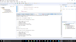
The monitor should be loaded into flash memory and run upon reset (i.e., it should function in a “turn key” fashion). The following welcome message should be displayed:
For simplicity, we will use single characters for each command. A “return” following the command string is required to “execute” it. The command set is as follows:
“M” or “m” memory editor for SRAM
“G” or “g” go (start execution) at given address
“D” or “d” display SRAM contents starting at given address
“R” or “r” display contents of all registers (including CCR)
If a valid command is entered, control should be transferred to the corresponding subprogram;
otherwise, an error message should be displayed, followed by a new prompt.
Memory Edit Command:
The memory edit (“M” or “m”) command starts a dialog that permits the user to modify the
contents of any 9S12C32 SRAM location (in the range of $3800 to $3FFF). The program should
begin by prompting the user to enter the (starting) address of the location in memory to be
modified (note: all values entered are assumed to be hexadecimal). If the value is outside the
range $3800-$3FFF, an error message should be displayed followed by re-prompting the user for
an address:
=>M
Memory edit mode…
Enter address: 37FF
ERROR – Invalid Address – Try Again…
Enter Address: 4000
ERROR – Invalid Address – Try Again…
Enter Address:
9S12C32 Mini-Monitor V1.0
Created by: your name and class number
Last updated: date code was last updated
=>
note that the character
sequence “=>” is used as the
monitor command prompt
ECE 362 – Experiment 4 Rev 1/13
Bigger Bytes Lab Manual -3- © 2013 by D. G. Meyer
Once a valid address is entered, the contents of that location should be displayed, followed by a
prompt for a new value for that location. If no new value is entered (i.e., the RETURN, a.k.a.
ENTER, key is pressed), the contents of the location should be unchanged and the memory
address should be incremented by one. If an invalid (i.e., non-hexadecimal) pair of digits is
entered, an error message should be displayed and the contents of the location should be
unchanged. Otherwise, the contents of the location should be changed to the “new” value and
the memory address should be incremented by one. The series of memory edits is stopped by
entering a period, which should cause the system to re-issue the “Enter address” prompt. Note
that editing should also stop if the lower or upper address limit of SRAM ($3800 and $3FFF,
respectively) is exceeded. Another special character that should be recognized is the minus sign:
if “-” is entered in response to “Enter new value”, the contents of the current location should be
unchanged and the address should decrement.
Enter address: 3900
(3900) = 8C
Enter new value: AK
ERROR – Invalid Data – Try Again…
(3900) = 8C
Enter new value: D7
(3901) = A5
Enter new value: <ret>
(3902) = B4
Enter new value: C9
(3903) = 44
Enter new value: .
Enter address: 3A00
(3A00) = 9A
Enter new value: 44
(3A01) = B9
Enter new value: –
(3A00) = 44
Enter new value: .
Enter address: .
Exit memory edit mode
Several things are worth noting. First, all addresses are assumed to be four hexadecimal digits.
These will be input as (exactly) four consecutive ASCII characters from the emulated terminal
keyboard using getword.
Second, all data values are assumed to be two hexadecimal digits. These will be input as
(exactly) two consecutive ASCII characters from the emulated terminal keyboard using
getbyte. Note that if an error (invalid hex digit) is detected by the ASCII-to-hex (atoh)
conversion routine, getbyte or getword will return with CF=1 (else, CF=0).
Third, be careful which locations you modify while testing your memory editor program. Note
that if you attempt to modify locations used directly by your application (variables stored in
SRAM or the stack area), very strange things will most likely happen!
(3900) ¬ D7
(3901) unchanged
(3902) ¬ C9
(3903) unchanged
(3900) unchanged
(3A00) ¬ 44
(3A01) unchanged
ECE 362 – Experiment 4 Rev 1/13
Bigger Bytes Lab Manual -4- © 2013 by D. G. Meyer
Go Command:
The go (“G” or “g”) command allows execution of a program that has been loaded into SRAM.
The user is prompted for the program starting address.
=>G
Enter program starting address: 0900
Display Command:
The display (“D” or “d”) command allows a fixed-size block of SRAM (128 bytes) to be
displayed on the screen (8 rows of 16 (two-digit) hex values), with the starting address of each
row displayed at the beginning of each line, along with a “column identifier” (see below). The
user is prompted for a 16-bit starting address (entered as four hex digits).
=>D
Enter SRAM starting address: 3900
0 1 2 3 4 5 6 7 8 9 A B C D E F
3900: 00 00 00 00 00 00 00 00 00 00 00 00 00 00 00 00
3910: 00 00 00 00 00 00 00 00 00 00 00 00 00 00 00 00
3920: 00 00 00 00 00 00 00 00 00 00 00 00 00 00 00 00
3930: 00 00 00 00 00 00 00 00 00 00 00 00 00 00 00 00
3940: 00 00 00 00 00 00 00 00 00 00 00 00 00 00 00 00
3950: 00 00 00 00 00 00 00 00 00 00 00 00 00 00 00 00
3960: 00 00 00 00 00 00 00 00 00 00 00 00 00 00 00 00
3970: 00 00 00 00 00 00 00 00 00 00 00 00 00 00 00 00
Register Command:
The register command (“R” or “r”) causes the current contents of all the CPU registers to be
displayed without affecting them. An illustration of the register display format that should be
used is shown below.
=>R
SXHINZVC (A):(B) (X) (Y) (SP) (PC)
11010000 12 34 12 34 12 34 09 F0 38 00
ECE 362 – Experiment 4 Rev 1/13
Bigger Bytes Lab Manual -5- © 2013 by D. G. Meyer
A Note on Grading:
The values of interest following the execution of the register print command (“=>r”) are
those that the registers have upon starting execution at main, unaffected by the prompt code. So,
the register values should be preserved (optimally via the stack) at the beginning of main and
restored upon (or just before) calling the register print routine. This also allows for a
standardized way of grading the register print command.
Here is how the “register print” command will be graded:
1. Use the “go” command (“=>g”) to jump to $3800, which executes a set of instructions
that set the registers and then returns to ‘main’.
2. Use the “register print” command (“=>r”) to check that it prints the register values as
defined by these instructions.
The result of Step 2 should be:
(D) = (A:B) = $1234
(X) = $ABCD
(Y) = $CDEF
(CCR) = %10101010
NOTE: This assumes that the code between org $8000 and main has not been changed.